
Wings

· 3 min read

Continued on a couple of tasks to finally close out everything that needs to be done on the wing, except we had to head to the hangar for these tasks. At this point, we needed to finish screwing in the wing tip and finish working on the wing tip access plates, as well as dropping the fuel tank again (!) for leak testing. Learned a couple of lessons the hard way on why it's important to finish as much as humanely possible before moving to the hangar. We're about 20-30 minutes away drive, and yes, both times we went out to the hangar we realized we needed different tools or parts that we didn't bring. We got the wingtips all screwed in at least, but will have to leave the fuel tanks to be dropped next time as I only had a long torque wrench with me and couldn't get at some of the bolts, need a shorter rachet socket wrench to get the required movement.

Cabin Top

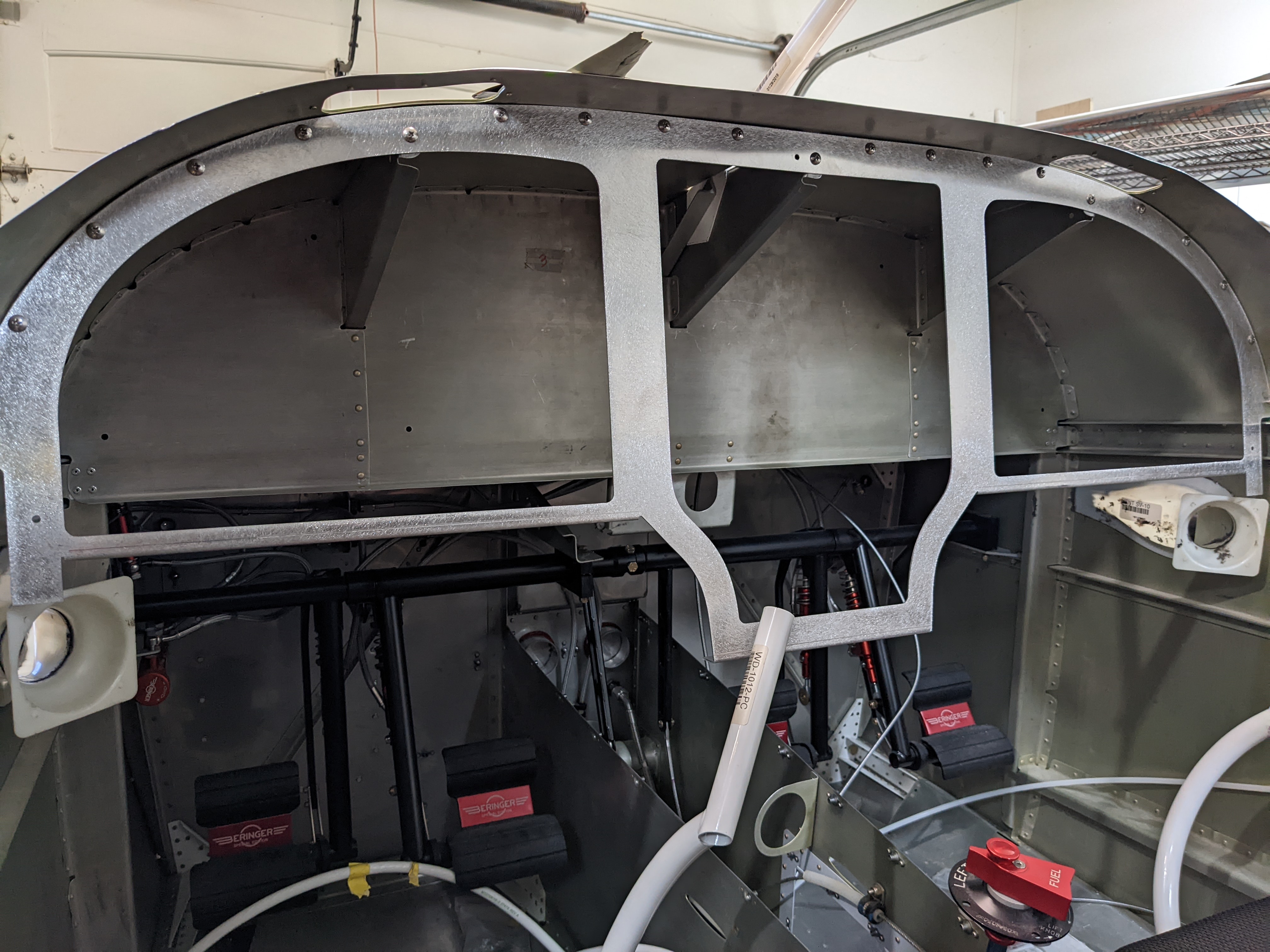
Working on a couple of items to finish up the cabin. At this point, we are rebuilding the seal channels again and again to get them in the correct position. When we sanded the cabin top we sanded the gutter flat on the outside but there is still a bit of a curve on the inside of the cabin top. When we put the seals with epoxy on there is a natural tendency for the seals to curve outwards following the door gutter curve. Not a big deal, just tedious to continously sand off and reapply to get the correct geometry. Once the seals are in a place we like them we'll install the gas strut bracket and finish up the planearound latch install, which should finally close out the doors!

Also have started on fitting the center console. The center console we received from Aerosport did not have the scribe line for the throttle quadrant cutout, so the first thing we did was to disassemble the entire quadrant to take out the levers. With that done, we used the quadrant itself as a guide to mark out the cutout on the center console. Once cut out, follow this video. However, instead of doing all this in the plane I was able to use a sharpie to mark the location of the sides of the center console in relation to the tunnel and then take it out of the plane to work. Also, since I'm using control approach pedals I needed to cut slots in the tunnel cover to fit. Since I had the pedals installed already and didn't want to unhook the rudder cables, I cut the cover in half about the midpoint of the second and third screw hole from the front which allowed me to fit the cover and the slots around the control arm. Next week: Duplicate tunnel cover holes in center console and locate throttle quadrant and fuel selector.

Cowl

Finishing up cowling as well. Top cowl we are using Skybolts for the top flange only, and sticking with hinges for the rest. Glassed in strips of carbon fiber on the top and bottom of the aft top cowl to increase stiffness and prevent pillowing in this area. Bottom cowl I had to open up the gear slot a lot more as contact with the nose gear has already stripped away a lot of the powder-coat. Plan is to spray an enamel coating once we are done with cowl fitting.

Wings

· 2 min read

This weekend finally finished the wings. They had come to me basically complete as quickbuild, but we needed to put in all the wiring and other items we needed in there before closing it up. Fairly simple, after a lot of off-plans work it was refreshing to come to a section where we could just follow the plans for the most part. For the right wing, with the amount of wires I had to run for the GSA28, the Ziptips, and the antenna I had to put in a whole new conduit. Tried multiple things. The standard wire conduits for cars won't work because there's enough movement through the ribs that wiring gets caught on the ribs when you try to feed it through. What I found was a good product was a 3/8" tube for fish tanks, totally smooth on the inside and very light. I tried multiple different methods of securing the conduit, from RTV to Lord Adhesive, and they all failed after a bit of movement to them. I will return to this area during final assembly and probably ziptie the conduits down to a couple of ribs in between to help secure it.

Riveting the bottom wing skin was very straight forward, although the plans could be a little more clear. We followed the plans very literally for the right wing and riveted the bottom wing skin aft to forward, row by row, which made the row of rivets to the main spar a pain to get to. On the left wing we just riveted it from the middle outwards, column by column. Much easier and basically doable with one person.

I terminate all my wire runs using Deutsch Connectors and then loaded the wing, cradle and all into a truck and moved it to the airport. A Penske 16ft truck will just about fit, but getting it up the ramp is difficult and the angle makes it likely you'll hit the top. We had to use our engine hoist to lift one end of the cradle so the entire cradle + wing assembly could go in horizontally.

Now off to transparencies and interiors!

Here's the wings sitting in the hangar:

Cabin Top Riveted

· 2 min read

Have been delaying this step for a long time now since I wanted to get as much done as possible in the tailcone before closing everything up. However, finally realized there would always be more to do. I got the ELT installed, NACA vents cut and installed, and then proceeded to close and rivet up the tailcone and cabintop. In the future, I'm still planning on installing the transponder and #2 COM radio there, and at least one battery will need to go back there. But that's future me's problem. Build on!

Panel Installation

In the same vein, starting to install the panel today. I had the panel built by Pacific Coast Avionics, using an Aerosport 310 Panel and it was delivered a month or so back.
All I did this weekend was to mount the aluminum panel subframe onto the fuselage. The instructions from Aerosport are unfortunately wrong for the product I received.

Instead, you'll notice the aluminum frame already has a hole drilled around this location. If you cut per the instructions, you can't capture this hole and you'll need to file away half of the height to actually fit behind the frame. Instead, cut straight from the top of the F-1003B bottom brace and include the nutplate already in place like this 
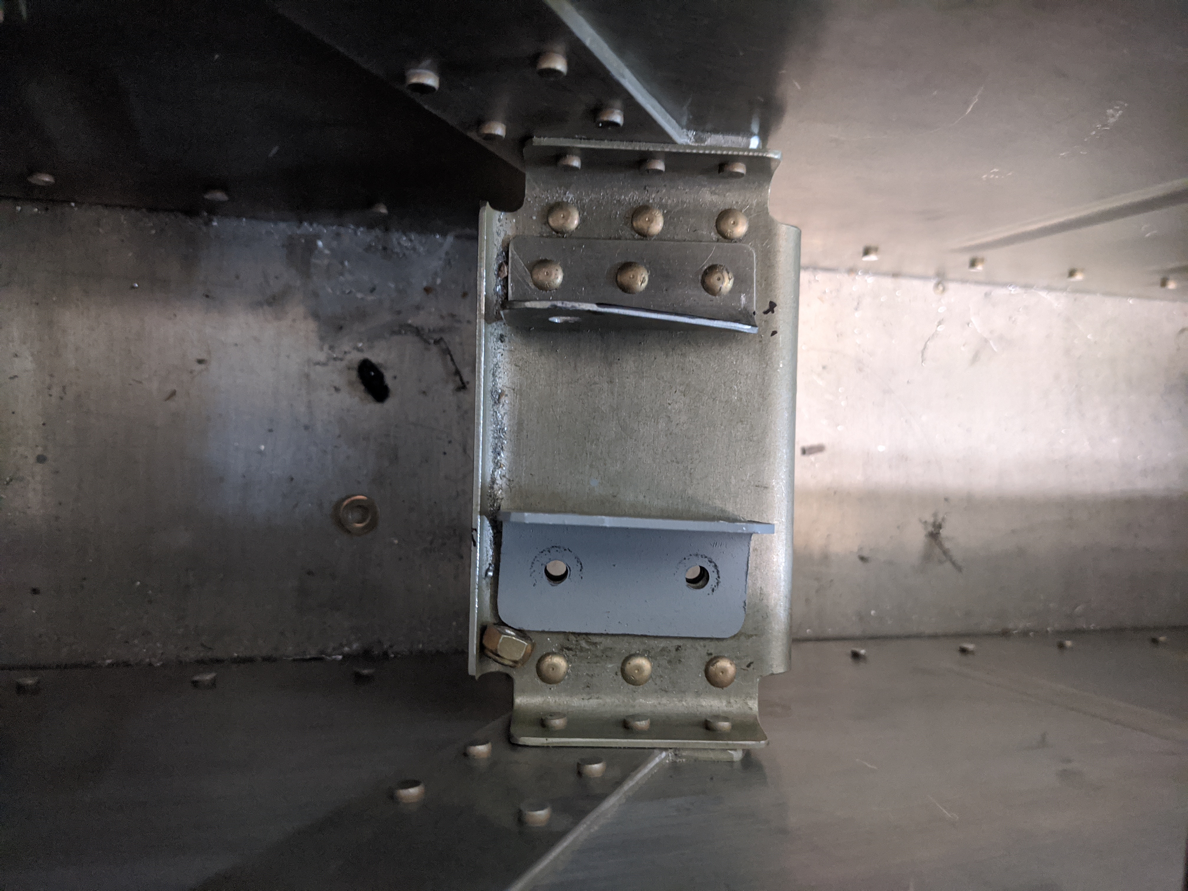
You can see the pre-drilled holes in place on the frame.

Prop Installation

· 2 min read

Got the prop a couple of weeks ago from Hartzell. Installation was fairly straightforward, althought I did have to cross reference the prop install manual and the Van's build instructions a couple of times. I used the Bogert Aviation Prop Sling to haul the prop into place, and then it was just six bolts to torque. I've mentioned this before but this is another one of those areas where having a torque wrench adapter pays off, made torquing the prop bolts a non-event.

Following Hartzell's manual, I used 0.032" safety wire to safety all the bolts, which as I understand is under the size of the usual 0.041" but since it's ok with Hartzell we'll see if whoever is doing the final inspection will see it as an issue.

Spinner

This is one of those areas where the kit just gets better. I obtained Hartzell's spinner cutout template from VAF but it turns out not only is the cutout already marked on the spinner, so are the screw holes. I opened the gap up the 1/4" from experience on VAF to prevent rubbing the prop if it vibrates, but otherwise it was very straightforward spinner install. Deburring was a PITA, nothing worked until I got a double edged deburring tool.

Engine Installation

· 2 min read

Have to say this was quite a surreal moment. I think I've just been working steadily at this project chipping away at it, but when the engine arrived it was really pretty surreal thinking how close we are to flying.

I above all else wanted an efficient engine, and I didn't care too much about going above 260HP as from everything I've read 260HP is plenty for the RV-10. I ended up getting a kit built engine from AeroSport Power up in BC. It's a standard IO-540 built from kits sold by Lycoming, except Aerosport was able to deliver the engine to me configured for SDS EFI. That saved a lot of time and hassle vs getting an engine from Lycoming then deleting mags myself, and it turned out cheaper! I received the engine via Freight in July, and we got an engine hoist from Harbor Freight + some straps to hoist it out and install. This turned out to be a three person job out of an abundance of caution, but nothing difficult. Because of the orientation of the straps we had to have two people maneuver the engine in place while the third installed and torqued the engine mounting bolts.

Gear, Brakes,and Wheels

· 2 min read

Gear Install

This was all in all a pretty simple install. I opted for the whole Beringer kit, but really not a lot of changes. Followed manual instructions to install gear legs. The only gotcha here is the shape of the receptacle, there is a "rim" close to the top of the gear tower. If you grease the gear leg like the instructions tell you to you'll hit the ledge and not be able to push it up any further and I spent a lot of time sanding and deburring the bottom opening of the gear tower thinking the powder coating on the inside is the issue. Pack grease not only on the outside of the gear leg, but also on the inside of the gear tower all the way down to where you can feel the tube expanding a bit and the gear leg should then go in with no fuss.

Beringer Wheels and Brakes

Moving on here this was pretty simple. The only place that needs a bit of thought is the orientation of the brake disc. I specifically asked Beringer support whether there was a specific orientation these needed to go and was told either way is fine. It was not fine. The flat side of the brake disc should face inboard to generate the required clearance. Other than that, install was a breeze. To mount the wheel fairings, you'll need the axle extensions sold by Aircraft Specialty. I also took this time to install jackpoints that mount onto the brake calipers from Flyboy Accessories. Indicate you have Beringer brakes and they will send you longer through bolts that fit Beringer brakes.

Nose Wheel

Nose wheel Beringer gives you a replacement axle for use with their wheel. Followed all instructions from Vans to install. Make sure the retaining "cup" for the nose gear shock absorbers is mounted the right way or you'll be wondering why you already have a gap in the elastomer pads.

antennas

· 3 min read

#Antenna Considerations: The following is compiled from Garmin install documents.

  1. GPS Antenna: a. GPS Antenna—Locate as far as possible from all COM antennas and all COM transceivers, ELT antennas, and DF antennas. The GPS antenna is less susceptible to harmonic interference if a 1.57542 GHz notch filter is installed on the COM transceiver antenna output. b. Locate the GDU as far as possible from all COM antennas 3 feet from any VHF COM Antenna 3 feet from antenna > 25 Watts of power at least 6 inches from other antennas (including GPS) c. two gps antennas should not be mounted in a straight line.
  2. COM Antenna: a. 6 feet from any DME or COM antennas, 4 feet from ADF sense antennas. b. As far as possible from ELT antennas. Never be less than 3 feet between COM. c. Recommended one antenna mounted on the bottom close to the front and the other on the top of the aircraft close to the tail.
  3. Transponder Antenna: a. Vertically attached to bottom of the aircraft. Not within three feet of ADF sense antenna or COM antenna. 6 feet away from DME antennas 3 feet of cable at least to GTX 45R

With that said, here's the layout I came up with.

Fairly simple layout. One GPS for the GTN and one GPS for the G3X, mounted in the overhead console in the cabin top, 1 foot apart, on either side of the centerline. Two COM antennas, both COMANT E-Series, one bent whip and one straight, mounted top and bottom. I'll mount the bent whip on the bottom of the aircraft in between the front seats in the tunnel. The top mount straight antenna will be mounted 4 feet from the rear GPS antenna in the tailcone. Transponder antenna, also COMANT E-Series, will be mounted on the bottom of the aircraft about 6 feet horizontal distance rearwards of the top mount COM antenna.

Finally, will aim to mount the ELT antenna under the fiberglass tailcone fairing horizontally. Never ending debate on this topic, but there's no guarantee you'll be upright when needing this antenna, and 406MGZ doesn't really require vertical polarization anyways.

For NAV/ILS/VOR, Archer NAV antenna in the right wingtip most likely. Will need AN509 screws and Garmin recommends DOW 738 to seal the antennas, although I will most likely wait until after paint to apply the sealant as the silicone messes with paint.

Doors & Cabintop

· 2 min read

The past few months have been spent wrapping up a lot of minor details and working on the doors/cabintop interface. Lots of work here and a significant amount has been deviating from the plans.

Here's the order I planned on for this part:

  1. Rough fit cabin top to fuselage done
  2. Build Doors and fit doors to opening done
  3. Fit overhead console done
  4. Permanently attach overhead console and switch pod working
  5. Install Airward Door Reinforcement
  6. Permanently install Cabin Top
  7. Install doors & door hardware
  8. Build lip for McMaster Carr Door Seals
  9. Install Windows & Windshield

With that said, a couple of notes. If I wanted to do over, I probably wouldn't buy and install the Airward door reinforcement kit. Nothing against the kit, it looks well made and sturdy. However, any deviation from plans costs time and money, and I'm not sure the risk of the door departing the aircraft, especially after the Planearound 3rd Latch solves the inflight issue, justifies the cost and extra time.

The doors are the one part so far where the plans are lacking. The location of the mounting holes for example are just straight up not where the plans said they would be. Use your best judgement and try your best to get it aligned. Nice thing with fiberglass is it's very hard to screw up enough to not be able to repair it.

I used a lot of other builders notes in this section to map out what I wanted to do. This thread was helpful keeping the door located in the correct position: https://vansairforce.net/community/showthread.php?t=175416

Tim's post here was helpful figuring out how to transition the overhead and switchpod to the cabin top.

Avionics

Went to Sun'n'Fun this year because I now need to seriously consider avionics. Will most likely go with some version of a G3X system, as the garmin interface just felt better to me. So Garmin system + EarthX batteries and maybe Mountain High Oxygen System is the purchases I'll need to make in the next few months.

PHAviation Flap Motor install

· 3 min read

Worked on installing the flap motor and flap system while waiting for my rudder pedals to arrive. Flap tubes are pretty much stock and didn't pose much issue, but the PHAviation flap motor took me longer than I expected.

I want to document this install as the current install manual isn't as detailed as VAN's.

First of all, here's the product in question. It's an all in one unit that saves you from wiring up a position sensor and has an integrated stop in the unit.

Here's the install manual that I'm working off of.

BOM

  • 1 AN5-23 Undrilled Bolt
  • 2 AN4-5A Bolts (I think)
  • 2 AN960-416 Washers
  • 6 AN3-5A/-4A Bolts (Use what length you think works)
  • 8 AN960-10L Washers
  • 1 MS24665-210 Cotter Pin
  • 1 AN310-5 Castle Nut
  • 1FT of 2024T3 0.5X0.65 Alum Tube
  • 1FT of 2024T3 1X1X1/16 Angle
  • 1FT of 2024T3 1.5X1.5X1/16 Angle
  • 4 K1000-3 Nutplates
  • 3 AN470AD4-5 rivets
  • 8 NAS1097AD3-3.5 rivets

Install Notes

To clarify, you're making potentially 6 pieces of angle:

  1. Left bracket
  2. Right bracket
  3. Left Upper Attachment angle
  4. Right Upper Attachment angle
  5. Left lower attachment angle
  6. Right lower attachment angle (maybe)

Here's some notes on stuff that I stumbled on while working off this install manual.

  • The two pictures on the first page show you what you'll need to make. On the left, you'll need to make 4 pieces of angle. The bottom two pieces (1) and (2) are made from 1X1X1/16 Angle and roughly need to be cut to around 3 inches long. It doesn't really matter, essentially the only controlling part is spacing the current flap motor mounting holes and the new holes 1.5 inches apart. (3) and (4) bolt onto (1) and (2) and are made from 1.5 X 1.5 X 1/16 angle. In the right picture, you'll need to fab a piece of angle to replace the left flap motor attach angle in the plane (this is (5)). This piece is attached via bolts, and is triangular in shape. Replace this piece with what is in the picture. The stuff in the left picture (1) & (2) will bolt on to the flap motor attach angles (5) and maybe (6).
  • Here's a pic of the left bracket:
  • If you don't have a 90 degree drill attachment and a short drill bit that will fit, you might as well go ahead and drill out the right flap motor attachment angle now. You can either replace it with an identical piece (6) to what you made for the left attachment angle (this is probably easier), or you can follow the instructions and drill a second smaller hole using the existing attachment angle.
  • You'll need to mount K1000-3 nutplates where the manual tells you to because you have to mount the new attachment angles (3) & (4) onto the flap motor and the entire assembly then gets bolted onto the bottom brackets (1) & (2). If you mount the new attachment angles to the bottom brackets first, you can't fit the AN5-23 bolt in.
  • Double check your measurements before drilling, don't put the brackets backwards like I did. The brackets extend the mounting holes towards the front of the aircraft.

Happy 244th Birthday!

· 3 min read

It's independence day! And about a month since my last update. Steady progress due to quarantine, knocking out little projects every day.

Empennage Attachment

I think in the last month, I wrapped up the empennage attachment section finally. Got a DC power adapter to bench test the trim servo, and it's incredibly satisfying when it actually moves. Not 100% done, as my trim tabs don't go the full 35 degrees nose down, but I'm leaving that for another day. I think I may need to pull the cables out of the HS and adjust the travel, which means I need to redo all my work there, including reattaching the cover plates and I just don't have the energy to tackle that again right now. Definitely have reverse travel at the top end, where my right trim tab continues to travel up and my left trim tab starts deflecting down again, so will need to look at that too.

Fuel system install

Started tackling the fuel system install too this month. Put in a tunnel access panel on the passenger side, which is all I think I need since only my fuel pump is going into this space. My two fuel filters are instead going to go in the wing root of each tank, which should allow for easier maintenance in the future and less spilled fuel in the cockpit. TS Flightlines put together my hose kit, and I'm installing per their install documents, planning for an SDS system. If you take this route, you'll need LP4-4 rivets for the fuel pump attachment angles as the thickness with the reinforcement plate is about 0.19 just a bit over the grip length of the LP4-3 rivets Vans specs in this location. Also, instead of following the instructions and cutting out the stock fuel selector attachment piece to fit the Andair valve, I cut a piece of aluminum and riveted it on instead. IMO this is superior as you don't need to do extra work cutting metal and the stock piece acts as a doubler. Here's a shot of the new piece I fabbed:

The circles are traced from the stock fuel selector attachment piece. Then I drew X's where I would drill rivet holes, put the new piece on top of the stock attachment plate and match drilled.

Next up, need to work out which hoses go where and put the fuel system in.